CATIA 3DEXPERIENCE · GENERATIVE SHAPE DESIGN · PARAMETRIC SURFACING
SURFACING
DEVELOPMENT
A collection of CATIA 3DEXPERIENCE surfacing exercises focused on parametric construction, aerodynamic geometry and robust model structure. The work was developed to improve my ability to create surfaces that can be modified quickly and reliably as design requirements evolve.
CATIA CAD DEVELOPMENT
GENERATIVE SHAPE DESIGN & ASSEMBLIES
This project focused on developing my CATIA 3DEXPERIENCE capability, particularly within Part Design, Generative Shape Design and Assembly Design. The objective was to create aerodynamic geometry that remained parametric, structured and efficient to modify.
The exercises below progress from wireframe-driven surfacing through more complete aerodynamic components and assemblies. Particular emphasis was placed on guides, sections, tangency control, trimmed surfaces and reference geometry so that changes could be made without rebuilding the model from the beginning.
CORE SURFACING PRINCIPLES
Build surfaces from controlled wireframes, guides and section geometry.
Use tangency and continuity constraints to maintain smooth aerodynamic form.
Drive geometry from reference planes and parameters for rapid iteration.
Structure models so components can be adjusted, replaced and reused efficiently.
VEHICLE BODY SURFACING
BODYWORK
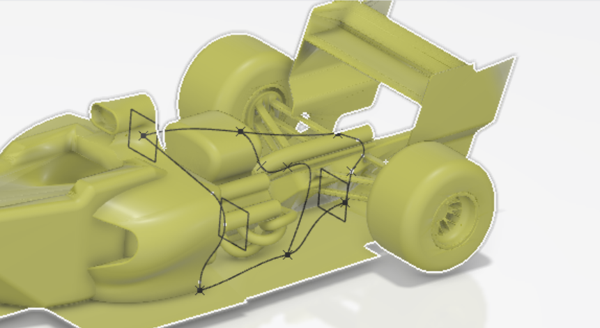
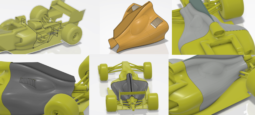
A flexible wireframe was created using sections and guides so the overall body shape could be changed efficiently. Tangency surfaces were used to preserve smooth transitions while the surrounding aerodynamic surfaces were developed around the reference vehicle geometry.
The work included the sidepod, blister, engine cover, airbox cover, shark-fin region and louvres. Separate trim geometry was also created where appropriate so features could be controlled independently.
Created a section-and-guide wireframe for controlled shape modification.
Applied tangency constraints to maintain surface continuity.
Integrated multiple bodywork features around the vehicle reference model.
Used separate trim geometry to improve modelling flexibility.
AERO COMPONENT DEVELOPMENT
T-WING
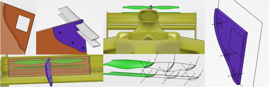
The T-wing exercise developed a more complete aerodynamic component from a controlled wireframe. Guide geometry and section curves were used to define the camber, thickness and local shape while retaining the ability to modify the aerodynamic profile.
The surrounding mount and interfaces were then developed using split surfaces, trimmed geometry and assembly-based construction so that the component could be positioned and adjusted within the vehicle model.
Built guide curves and sections to control the aerofoil geometry.
Used multi-section surfaces to generate the primary wing form.
Created split and trimmed surfaces for the mounting interfaces.
Developed a reusable component suitable for rapid geometric iteration.
SURFACE TRANSITION
ADAPTOR
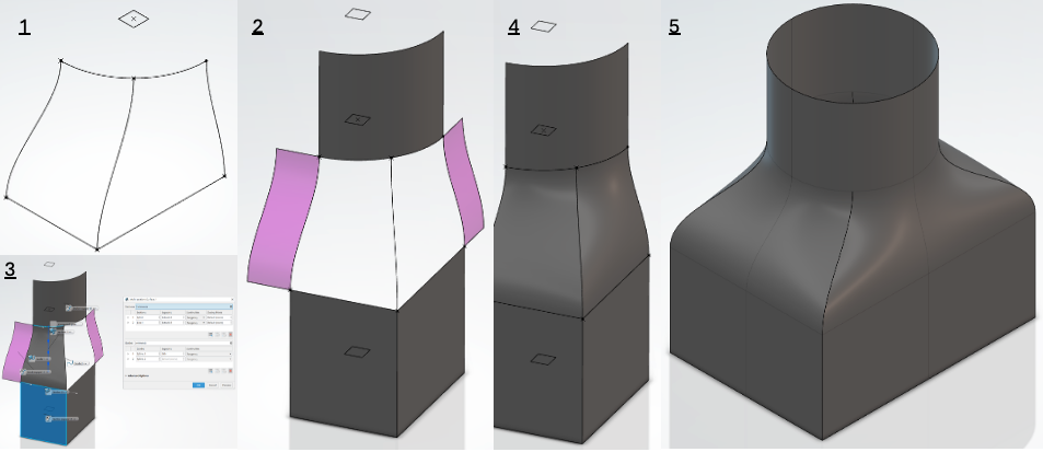
This exercise focused on joining dissimilar sections while maintaining smooth surface transitions. The adaptor was developed from a circular profile into a more rectangular lower section using controlled guide and tangency geometry.
Symmetry and linked reference planes were used to reduce unnecessary modelling work and make the height and offset of the transition easier to adjust.
Defined circular and lower-section boundary geometry.
Used tangency surfaces to create smooth transitions between profiles.
Modelled a quarter of the part and used symmetry to complete the geometry.
Linked construction planes to allow quick dimensional changes.
AERODYNAMIC COMPONENT
FRONT WING
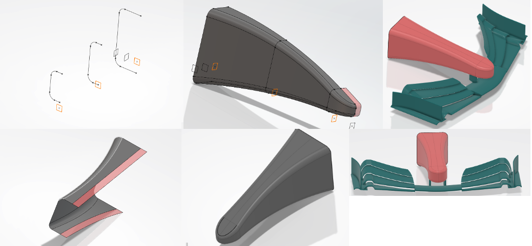
The front-wing exercise concentrated on building an aerodynamic element from defined leading edge, trailing edge and section geometry. Surface construction was driven by the underlying curves so the profile could be modified without recreating the complete surface.
Multi-section surfaces and local tip geometry were used to maintain a controlled shape across the span while preserving a clean, editable CATIA model structure.
Defined aerofoil sections and guide curves from reference geometry.
Generated the wing using multi-section surfacing.
Controlled tip and edge transitions using tangent construction.
MODEL DEVELOPMENT
WIND TUNNEL MODEL
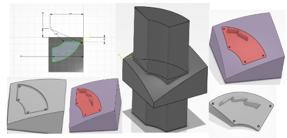
This exercise moved from pure surfacing into model-definition work for a wind-tunnel application. A removable sidepod-style component was developed so geometry could be swapped efficiently between configurations during testing.
The design was split to follow the intended vane curvature while avoiding interference with surrounding geometry. Manufacturing considerations were included, with a nominal 0.1 mm allowance used for fit.
Defined a removable component around the required aerodynamic surface.
Used split and closed-surface methods to create the final solid.
Designed the interface for quick component changes during testing.
Included a 0.1 mm manufacturing allowance for fit.
AERODYNAMIC SURFACING
REAR WING
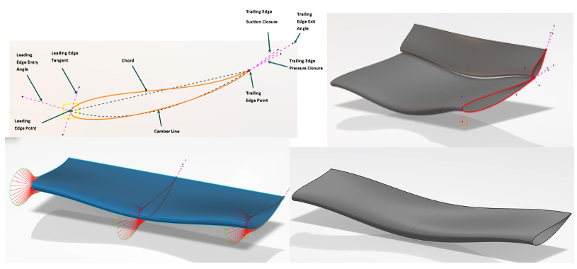
The rear-wing work developed a multi-element aerodynamic assembly using parametrically controlled profiles and guide curves. The emphasis was on maintaining clean surface continuity while allowing the main geometric characteristics to be changed efficiently.
The component was treated as an aerodynamic assembly rather than an isolated surface, with attention paid to element relationships, local sections and the overall spanwise form.
Constructed profile and guide geometry for the wing elements.
Generated surfaces with controlled continuity across the span.
Managed the relationship between multiple aerodynamic elements.
COMPLEX TUBE SURFACING
V6 EXHAUST
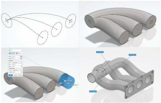
The V6 exhaust exercise applied the same parametric principles to complex tubular geometry. A wireframe of points, planes and splines was created first so the routing could be adjusted without rebuilding the complete manifold.
Circular profiles were then swept along the spline routes before the individual runners were integrated with the flange and surrounding mounting features.
Created the exhaust routing from points, planes and spline geometry.
Used circular profiles along the spline paths to form the runners.
Added flange and sensor-mounting geometry to complete the assembly.
Maintained a parametric wireframe so routing changes propagated through the model.
AERODYNAMIC SURFACING
RWEP UPPER
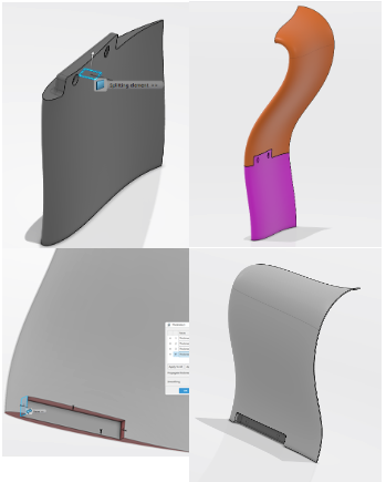
This exercise focused on constructing a controlled aerodynamic surface from wireframes and guide geometry. The geometry was developed to be adjustable through its defining sections rather than through direct surface editing.
Leading- and trailing-edge definition, local section control and smooth transitions were used to create a robust upper aerodynamic surface that could be iterated without losing continuity.
Developed the initial wireframe and section strategy.
Controlled leading and trailing edge geometry using guides.
Used multi-section surfacing to generate the final aerodynamic form.
PROJECT OUTCOME
FROM WIREFRAME TO ROBUST PARAMETRIC SURFACES
Developed a stronger understanding of wireframe-driven surface construction within CATIA 3DEXPERIENCE.
Applied tangency, continuity and guide-based modelling to aerodynamic and complex mechanical geometry.
Built models around parameters and reference geometry so design changes could be made quickly without rebuilding the complete part.
The main value of this work was learning to treat surfacing as a controlled engineering process rather than simply creating visually smooth geometry. Building robust wireframes, guides and references made the models easier to modify and much closer to the iterative workflows used in aerodynamic development.