
MECHANICAL DESIGN · CAD · VEHICLE INTEGRATION
REAR
SUSPENSION
Development of a rear suspension and wheel-end assembly, combining suspension geometry, MATLAB-based kinematic definition, component design, packaging and production-ready engineering drawings.
DESIGN CHALLENGE
FROM VEHICLE TARGETS TO GEOMETRY
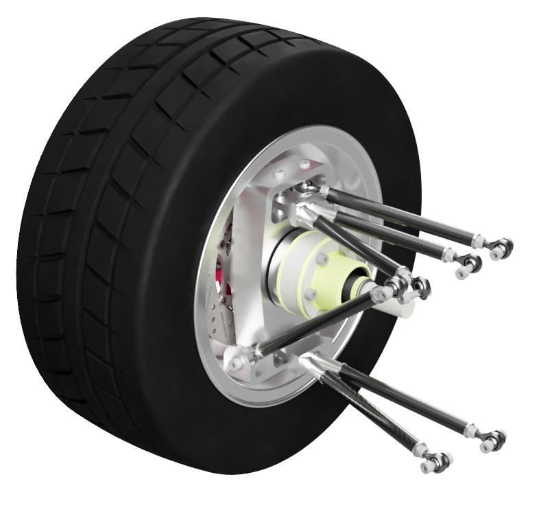
The rear suspension was developed as an integrated vehicle system rather than a collection of isolated CAD parts. Suspension geometry, wheel-end packaging, load paths, manufacturability and serviceability therefore had to be considered together.
A key part of the workflow was translating vehicle-level geometry into defined suspension pickup points before progressing into detailed component and assembly design.
KINEMATIC DEFINITION
MATLAB SPLINE & PICKUP-POINT DEVELOPMENT
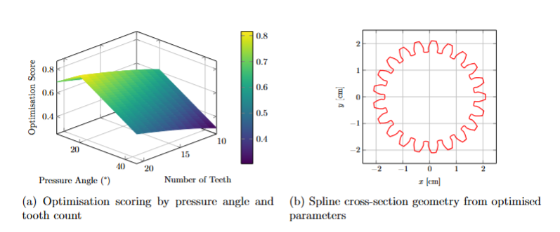
MATLAB was used as an engineering tool to calculate and manipulate suspension geometry before the final CAD architecture was fixed. The calculator created a repeatable link between numerical geometry definition and the physical suspension layout.
Rather than positioning links visually in CAD, the suspension could be defined from calculated coordinates and geometry changes applied systematically.
NUMERICAL → PHYSICAL
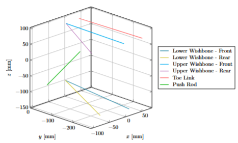
CONNECTION POINTS IN 3D SPACE
The calculated coordinates establish the hard-point architecture for the suspension links and upright, directly bridging the numerical study and final CAD model.
CAD DEVELOPMENT
UPRIGHT & SUSPENSION ARCHITECTURE
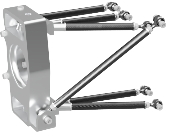
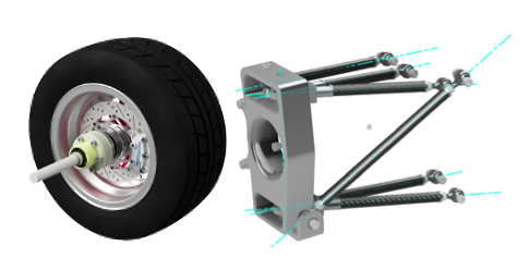
With the hard points established, the suspension was developed around the upright and wheel-end package. The link architecture had to preserve the intended geometry while providing realistic component interfaces and clear load paths.
Packaging was considered alongside component access, joint orientation and the relationship between the upright, wishbones and wheel-end hardware.
COMPONENT DEVELOPMENT
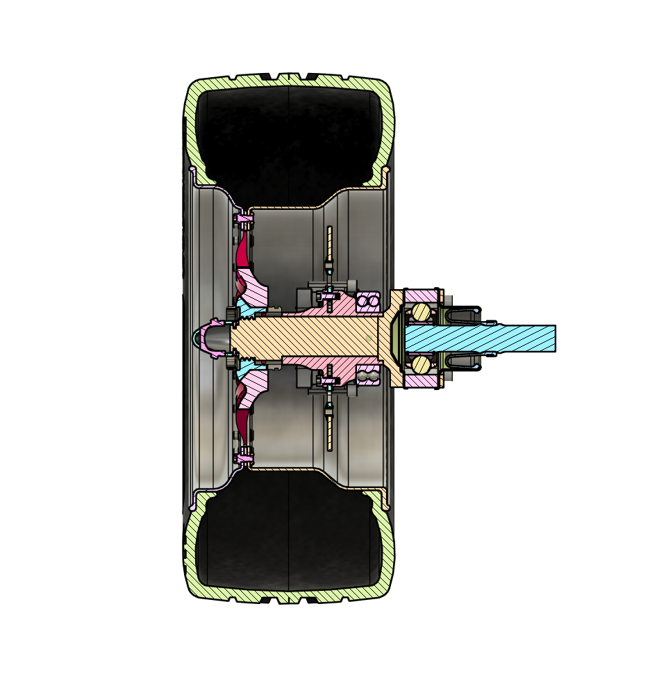
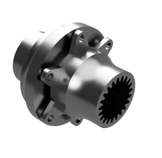
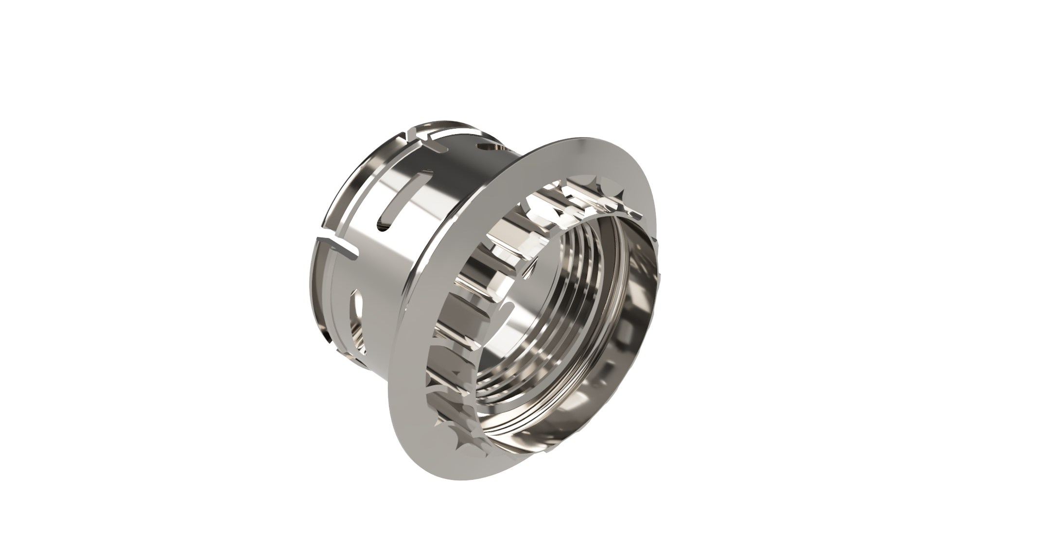
WHEEL-END INTEGRATION
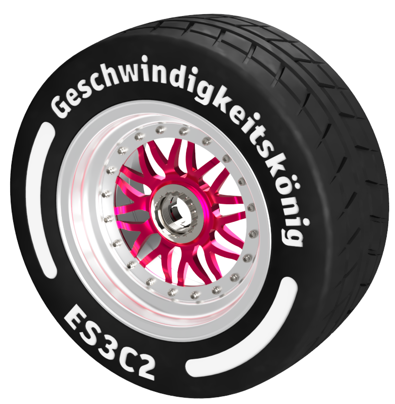
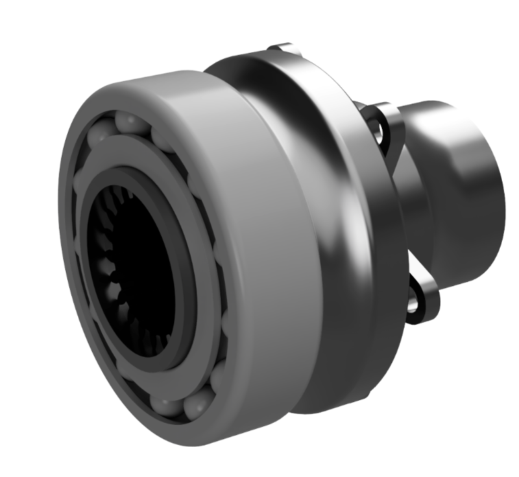
DESIGN JUSTIFICATION
DETAILING THE WHEEL END
ENGINEERING DEFINITION
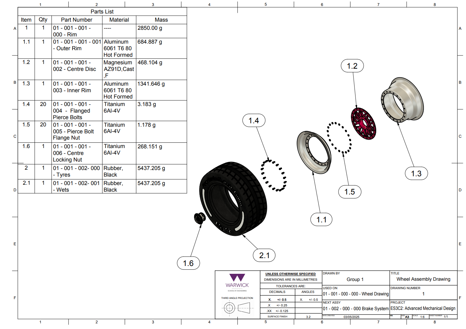
ASSEMBLY & PRODUCTION DRAWINGS
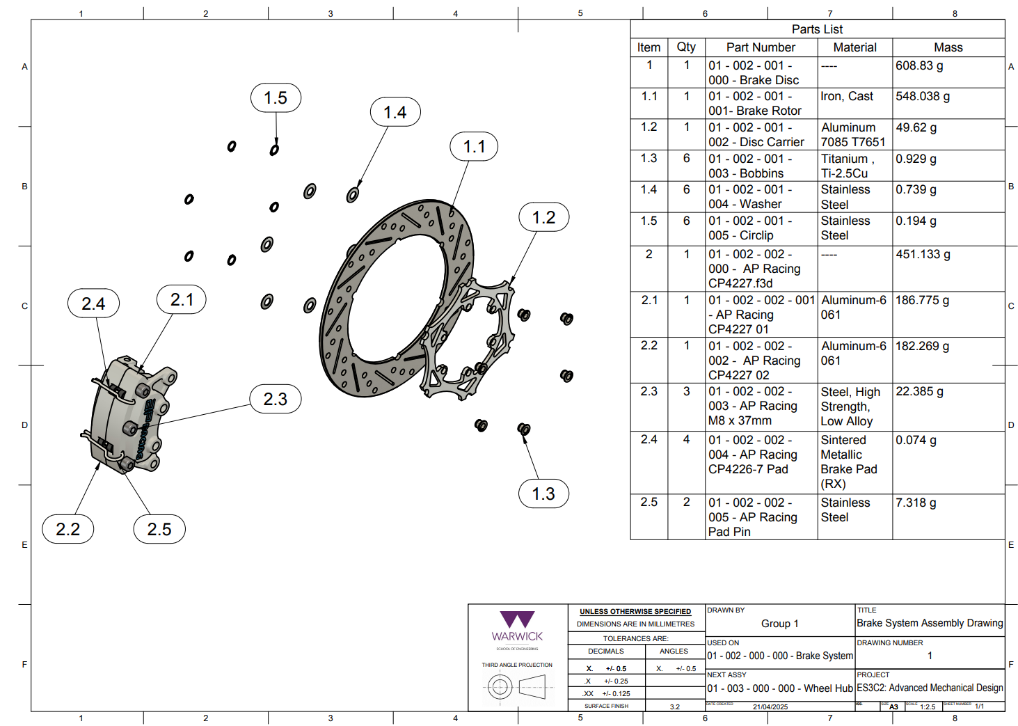
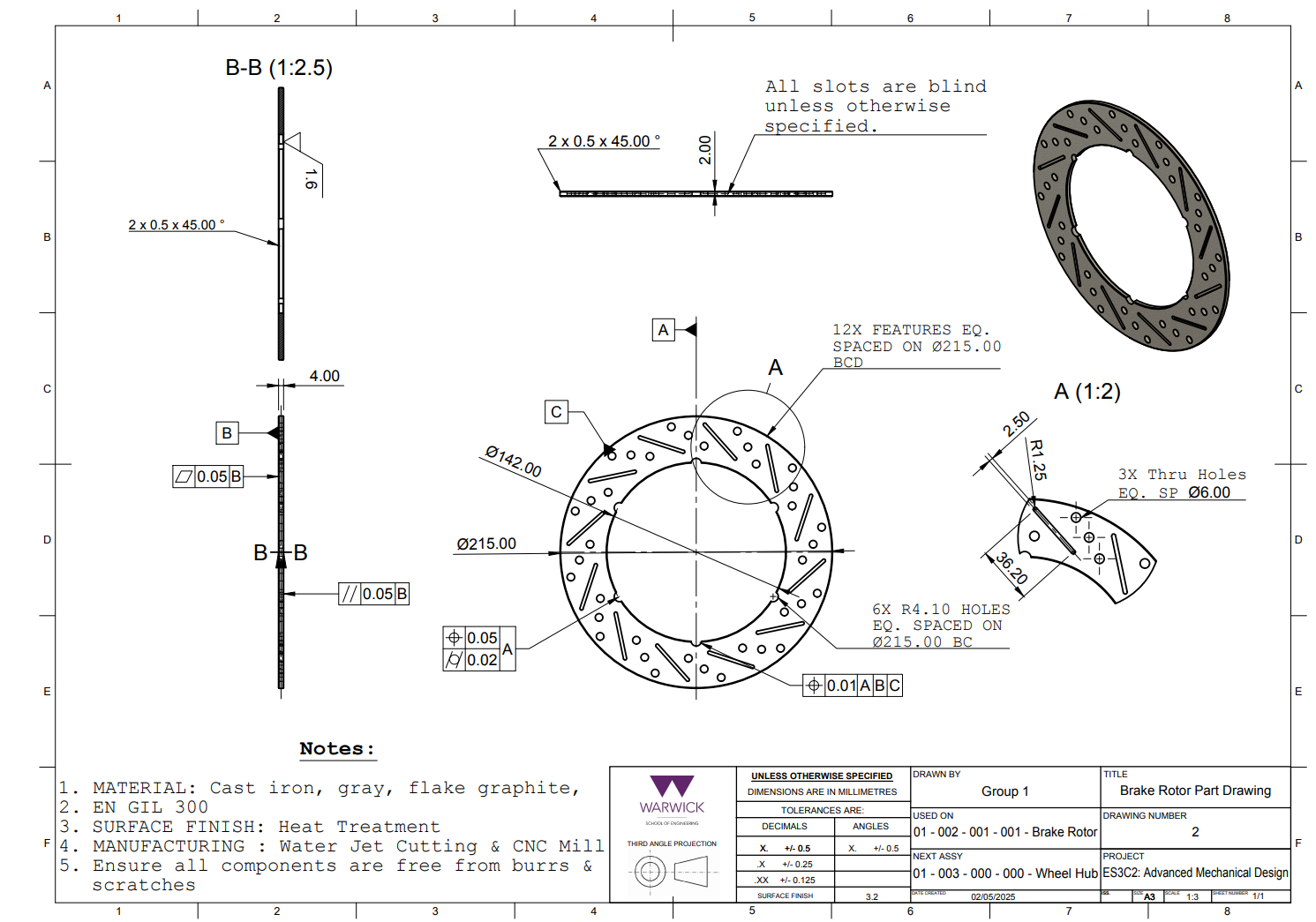
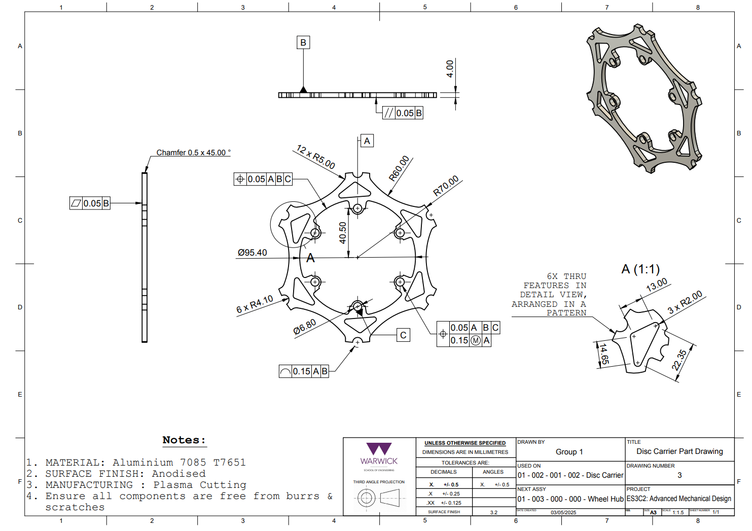
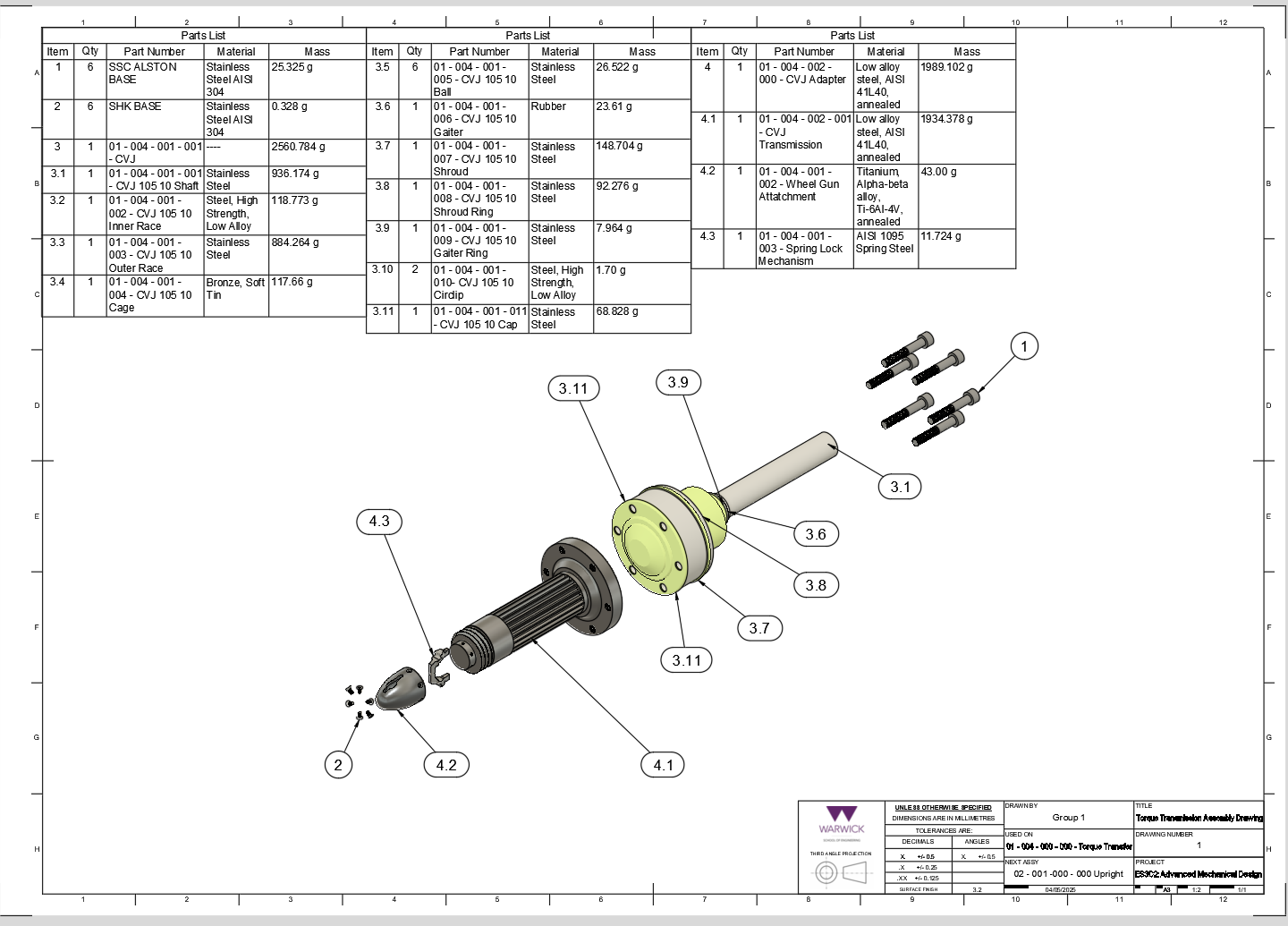
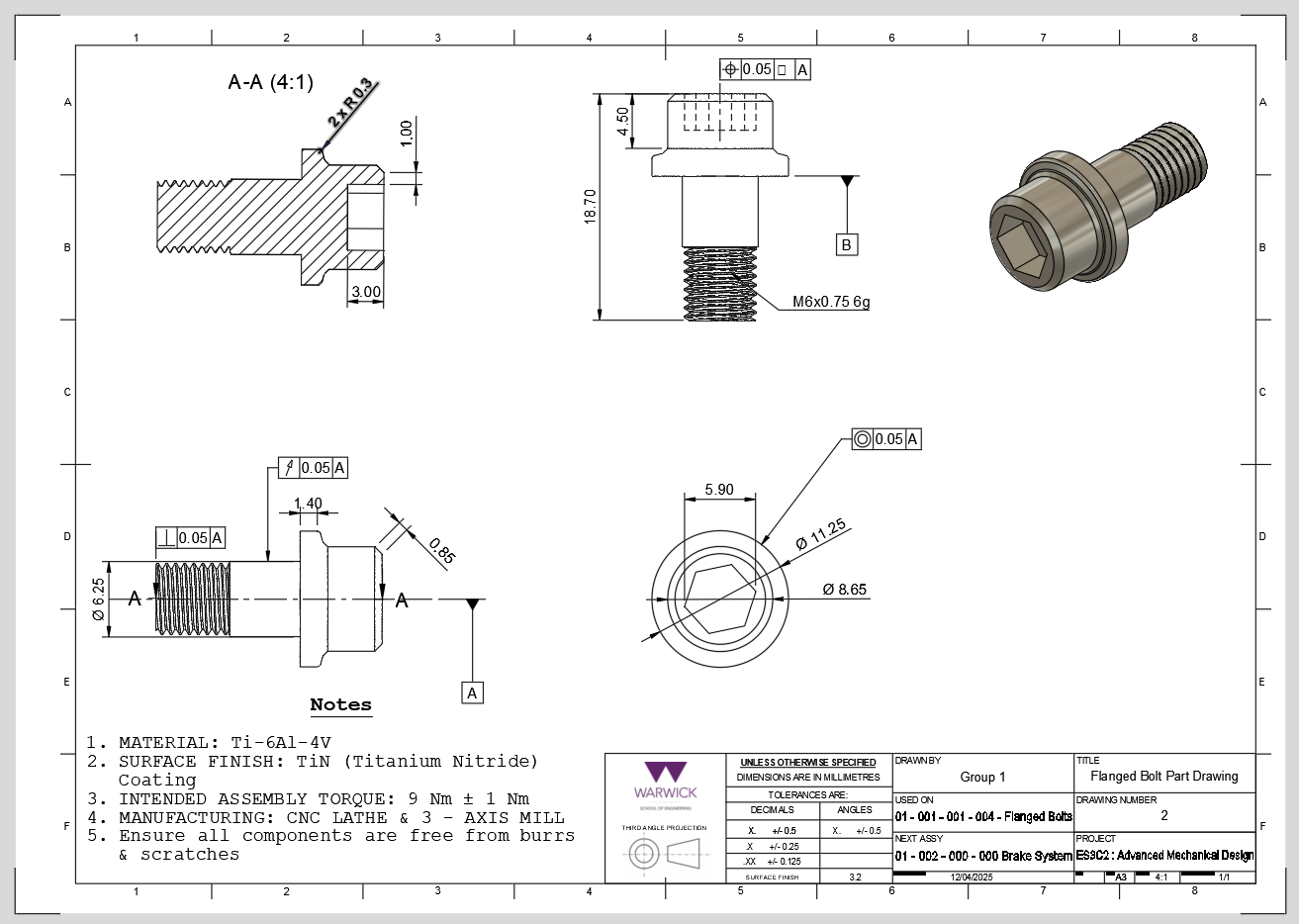
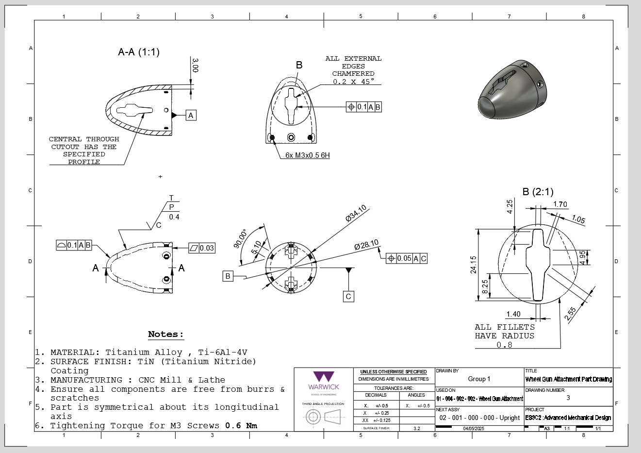
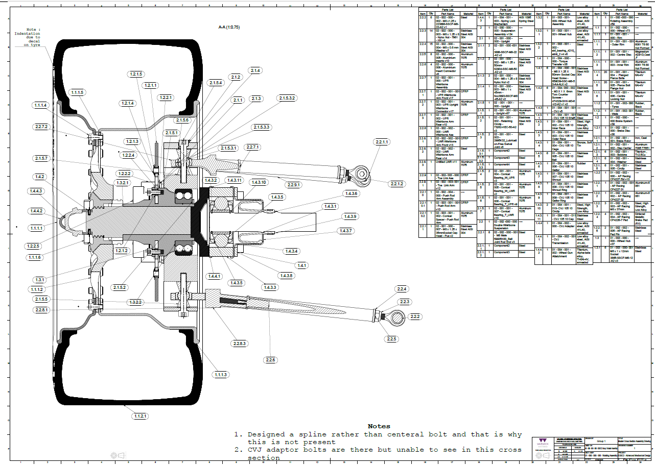
The final CAD was translated into assembly and part drawings to communicate component interfaces, materials, tolerances and manufacturing intent. The set demonstrates GD&T, datums, section views, bills of materials and assembly definition.
PROJECT OUTCOME
FROM CALCULATION TO ENGINEERING DEFINITION
Used MATLAB to support suspension geometry and translate calculated results into CAD hard points.
Developed an integrated suspension and wheel-end architecture around component and packaging constraints.
Produced detailed part and assembly drawings communicating manufacturing and GD&T requirements.
“The strongest part of this project was connecting calculation, analysis and CAD rather than treating them as separate activities. The suspension geometry informed the physical architecture, while the final drawings forced the design to be considered at a manufacturable component level.”