VEHICLE DESIGN · STEERING · SUSPENSION · AERODYNAMICS
FORMULA ELECTRIC
MOTORSPORT CAR
An international engineering internship project focused on the development of an electric formula-style race car, combining steering geometry, suspension design, component CAD and introductory aerodynamic simulation.
EUROP EDUCATION
VEHICLE DEVELOPMENT WITHIN AN INTERNATIONAL TEAM
During the internship, I worked with an international engineering team on the development of an electric race car. My main responsibility was the steering and suspension system, with additional work supporting the aerodynamic package.
The project combined analytical calculations with CAD development and simulation, giving me an early opportunity to connect engineering theory with vehicle-level design decisions.
MY CONTRIBUTION
Develop steering geometry using Ackermann principles.
Design steering and suspension components in CAD.
Develop an upright suitable for subtractive manufacturing.
Support front- and rear-wing development using aerodynamic simulation.
STEERING GEOMETRY
ACKERMANN STEERING CALCULATIONS
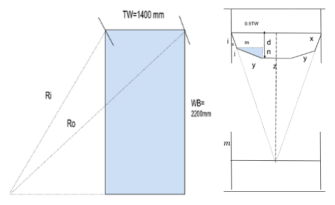
Before developing the steering system in CAD, I defined the geometry analytically. The calculations established the outside-wheel angle, turning radii, Ackermann-arm orientation and tie-rod geometry from the vehicle dimensions.
INPUT ASSUMPTIONS
Inner turning wheel angle = 40°
Ackermann arm length = 125 mm
Rack length = 420 mm
Rack-axis distance from front axle = 200 mm
Steering ratio = 4:1
Pinion module = 2.5
Track width = 1400 mm
Wheelbase = 2200 mm
TURNING GEOMETRY
The inner-wheel angle was first used to locate the instantaneous turning centre relative to the vehicle centreline.
tan(θ) = WB / e
tan(40°) = 2200 / e
e = 2621.06 mm
INNER & OUTER TURNING RADII
Rᵢ = √(WB² + e²)
Rᵢ = √(2200² + 2621.06²)
Rᵢ = 3422.59 mm
Rₒ = √[WB² + (e + TW)²]
Rₒ = √[2200² + (2621.06 + 1400)²]
Rₒ = 4584.25 mm
OUTSIDE-WHEEL ANGLE
Using the outer turning radius, the corresponding outside-wheel steering angle was calculated.
sin(φ) = WB / Rₒ
sin(φ) = 2200 / 4584.25
φ = 28.67°
ACKERMANN ARM ANGLE
The steering-arm angle was then defined from half the track width and the wheelbase.
tan(β) = (0.5 × TW) / WB
tan(β) = (0.5 × 1400) / 2200
β = 17.65° ≈ 17°
ACKERMANN ARM COMPONENTS
The 125 mm Ackermann arm was resolved into longitudinal and lateral components using the calculated arm angle.
l = x cos(β)
l = 125 cos(17°) = 119.538 mm
j = x sin(β)
j = 125 sin(17°) = 36.546 mm
RACK-TO-STEERING-ARM GEOMETRY
m = 0.5(TW − z) − j
m = 0.5(1400 − 420) − 36.546
m = 453.454 mm
n = d − l
n = 200 − 119.538 = 80.462 mm
TIE-ROD LENGTH
The final tie-rod length was obtained from the resolved lateral and longitudinal offsets.
y = √(m² + n²)
y = √(453.454² + 80.462²)
y = 460.537 mm
CALCULATED STEERING DEFINITION
Outside wheel angle = 28.67°
Ackermann arm angle ≈ 17°
Longitudinal arm component = 119.538 mm
Lateral arm component = 36.546 mm
Lateral rack-to-arm offset = 453.454 mm
Longitudinal rack-to-arm offset = 80.462 mm
Calculated tie-rod length = 460.537 mm
CAD DEVELOPMENT
FROM CALCULATED GEOMETRY TO STEERING HARDWARE
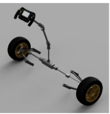
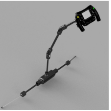
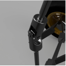
The calculated steering geometry was translated into a complete steering system, including the rack, column and wheel-end connections.
SUSPENSION DESIGN
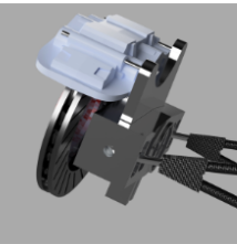
WHEEL-END & UPRIGHT DEVELOPMENT
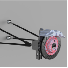
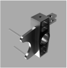
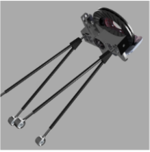
Alongside the steering system, I contributed to the suspension and wheel-end design. The upright was developed with subtractive manufacturing in mind, with the aim of maintaining stiffness while reducing unnecessary material and component mass.
The surrounding suspension geometry was then assembled around the wheel-end to check component relationships and vehicle integration.
AERODYNAMIC DEVELOPMENT
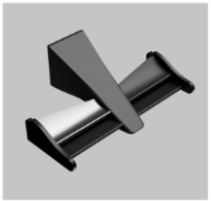
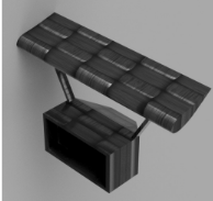
FRONT & REAR WING CONCEPTS
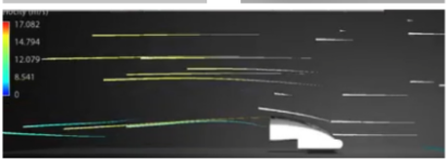
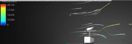
I also supported the vehicle's aerodynamic development by producing front- and rear-wing concepts and using Autodesk Flow Design to visualise the surrounding airflow.
PROJECT OUTCOME
CONNECTING CALCULATION, CAD & SIMULATION
Applied Ackermann steering theory and vehicle dimensions to calculate steering geometry before developing the system in CAD.
Developed steering, suspension and upright components as part of a wider electric race-car package.
Used introductory aerodynamic simulation to assess front- and rear-wing concepts and support vehicle-level development.
Working within an international team gave me an early appreciation of how analytical calculations, CAD and simulation come together in vehicle development. The steering work was particularly valuable because the geometry was first defined mathematically and then translated into a physical mechanical system.