MECHANICAL DESIGN · CAD · DRIVETRAIN
DIFFERENTIAL
GEARBOX
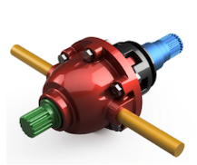
Development of a differential gearbox assembly to build my understanding of drivetrain architecture, gear meshing, CAD joints and mechanical motion within Autodesk Fusion 360.
PROJECT OBJECTIVE
UNDERSTANDING DIFFERENTIAL ARCHITECTURE
This personal project was undertaken after learning about differentials within my engineering studies, with the additional goal of developing my CAD skills through the creation of a complete drivetrain assembly.
The project focused on creating and meshing gears while developing a better understanding of the key components within a differential. Rather than treating the parts as isolated CAD models, the assembly was used to explore how the gears, shafts and housing interact as a mechanical system.
PROJECT FOCUS
Develop the individual differential components in CAD.
Build the components into a structured mechanical assembly.
Apply joints and gear relationships to reproduce drivetrain motion.
Use sectional and exploded views to communicate the final design.
CAD & MECHANISM DEVELOPMENT
GEAR MESHING, JOINTS & ASSEMBLY
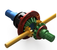
The differential was developed from individual components before being brought together into a complete Fusion 360 assembly. This provided an opportunity to improve my approach to assembly organisation and to understand the relationships required between moving components.
Rotational joints and gear relationships were then used to simulate motion through the gear set. Building a functioning mechanism helped deepen my understanding of Fusion 360 joint functionality as well as the mechanical interaction between the differential components.
Model and position the gears, shafts and housing components.
Define the required rotational joints within the assembly.
Establish gear relationships between the mating components.
Simulate the mechanism to assess the assembled motion.
DESIGN COMMUNICATION
SECTIONAL ANALYSIS
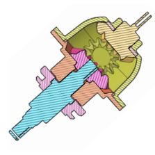
A sectional view was produced to make the internal architecture of the differential easier to understand. Removing the visual obstruction of the outer housing exposes the relationship between the shafts, internal gears and surrounding components.
This view complements the rendered CAD model by communicating how the mechanism is packaged internally rather than showing only the external form of the assembly.
ASSEMBLY DEFINITION
EXPLODED VIEW & PART STRUCTURE
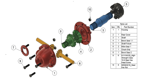
The exploded assembly was produced to communicate how the individual components combine to form the complete mechanism. Separating the parts makes the relationship between the housing, shafts, gears and fasteners much clearer than in the assembled render alone.
A corresponding parts list was included to identify the principal components and reinforce a more structured approach to CAD assembly management and design communication.
PROJECT OUTCOME
DEVELOPING A STRONGER CAD WORKFLOW
Developed a complete differential gearbox assembly from individual drivetrain components.
Improved my understanding of Fusion 360 joints, gear relationships and motion within mechanical assemblies.
Used rendered, sectional and exploded views to communicate the differential architecture and component relationships.
This project was an early step in developing my CAD workflow. It moved my focus beyond modelling individual components and towards understanding how parts are organised, constrained and made to interact within a complete mechanical system.