FEA-driven optimisation of an automotive transmission shift fork,
reducing component mass while satisfying structural stiffness,
strength and operational loading requirements.
The objective was to minimise the mass of an automotive transmission
shift fork without compromising structural integrity or functional
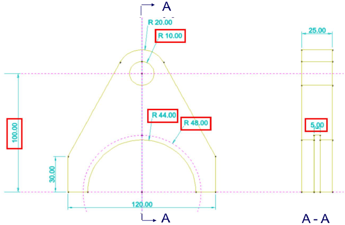
stiffness. The geometry had to remain within the original packaging
envelope while retaining fixed interface dimensions.
1259 N operational load
±0.25 mm maximum axial deflection
Stress below material yield strength
Fixed interface geometry retained
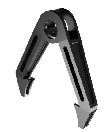
Initial design and key geometry
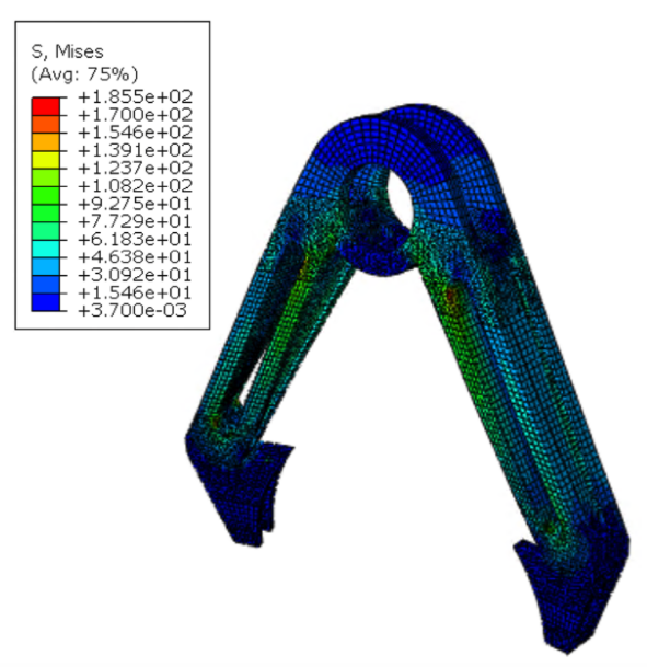
Representative non-linear FEA result
02
SIMULATION METHODOLOGY
01
CAD
Fusion 360
→
02
PARTITION
Geometry preparation
→
03
MESH
Structured / hybrid
→
04
CONTACT
Rigid sleeve model
→
05
NON-LINEAR FEA
Abaqus
→
06
ITERATE
Mass / stiffness trade-off
The non-linear model used a rigid disc to represent the shift sleeve,
with hard frictionless contact used to capture load transfer into the
fork legs more realistically than a simple distributed surface load.
03
MESH DEVELOPMENT
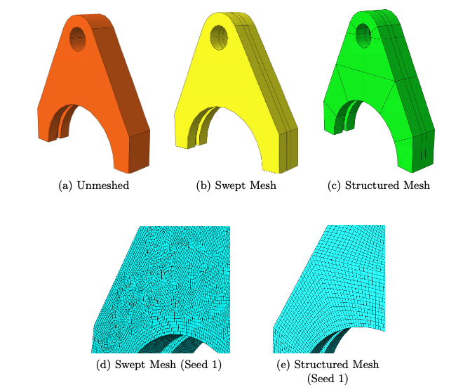
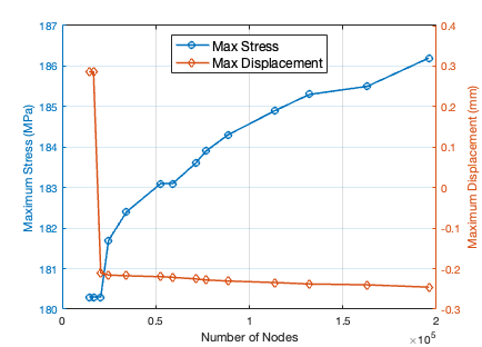
Geometry partitioning was used to improve element regularity and support
a higher-quality mesh. Mesh refinement was then assessed to ensure the
structural response was not being driven by element size.
≈ 1.2 × 10
5
nodes
Solution stability achieved beyond this region
Partitioning and mesh development
Mesh convergence study
04
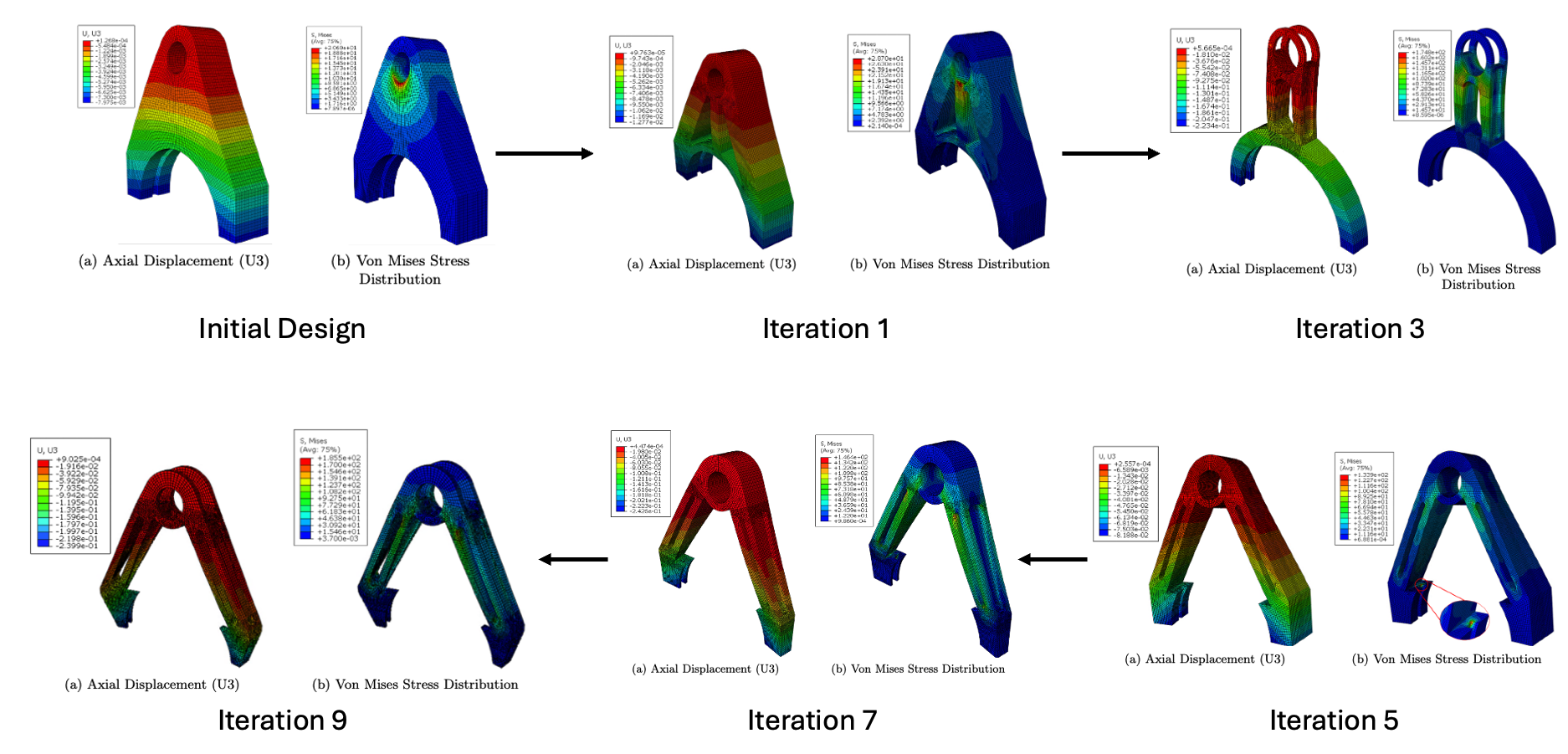
DESIGN ITERATION
Simulation results were used to progressively remove material from
low-stress regions while monitoring stress, displacement and contact
behaviour. The design evolved until stiffness became the limiting
constraint on further lightweighting.
Representative design evolution from baseline to final geometry
INITIAL DESIGN
1.28 kg
→
FINAL DESIGN
188 g
85.3%
MASS REDUCTION
05
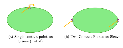
CONTACT MODELLING
The original single-contact configuration introduced an unrealistic
turning moment into the simulated sleeve. The contact arrangement
was therefore revised to create a more representative axial loading
condition and improve the physical relevance of the model.
Initial single-point contact vs improved dual-contact representation
06
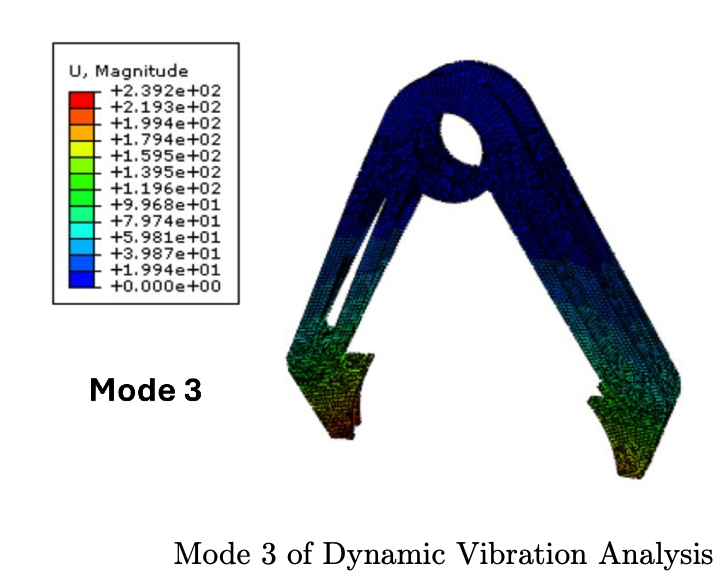
DYNAMIC ANALYSIS
Modal analysis was used to identify the vibration mode most relevant
to the operational loading direction. Mode 3 was selected from the
effective-mass response in the Z-direction.
1-DOF CHECK
k
eq
= F / y
max
f = 1 / (2π) √(k
eq
/ m)
FEA
1801.2 Hz
1-DOF estimate
682.3 Hz
The analytical estimate is intentionally simple and does not capture
distributed mass, spatially varying stiffness or higher-order modes.
Mode 3 — dominant response in the operational direction
07
STATIC VALIDATION
The final geometry was approximated as a cantilever beam to provide
first-order checks on displacement and bending stress.
DEFLECTION
y
max
= Pa
3
/ 6EI · (3L/a − 1)
Analytical: 0.2996 mm
BENDING STRESS
σ
max
= My / I = Pah / 2I
Analytical: 173.2 MPa
Check
Analytical result
Comparison with FEA
Maximum stress
173.2 MPa
7.1% difference
Maximum displacement
0.2996 mm
24.9% difference
Natural frequency
682.3 Hz
FEA: 1801.2 Hz · report records 90.1% difference*
*The dynamic comparison is a sanity check only: the 1-DOF model is too
simplified to reproduce the component's multi-mode structural behaviour.
08
KEY TAKEAWAYS
01
SIGNIFICANT LIGHTWEIGHTING
An 85.3% reduction in mass was achieved through
FEA-guided geometry optimisation.
02
MODEL FIDELITY
Contact modelling and mesh convergence were critical
to producing reliable and representative results.
03
ENGINEERING VALIDATION
Analytical calculations provided a useful sanity check
while highlighting the limitations of simplified models.
“This project reinforced the importance of treating simulation
as part of an engineering process rather than simply an output.
Model assumptions, contact representation and validation all
influenced the confidence that could be placed in the final design.”