Simulation-led optimisation and experimental validation of a CFRP
motorsport suspension pull rod, investigating laminate thickness
and ply orientation under tensile and torsional loading.
2.5 kN
AXIAL LOAD
2.7 Nm
TORSIONAL LOAD
3 PLIES
TENSILE OPTIMUM
≈ 36 kN
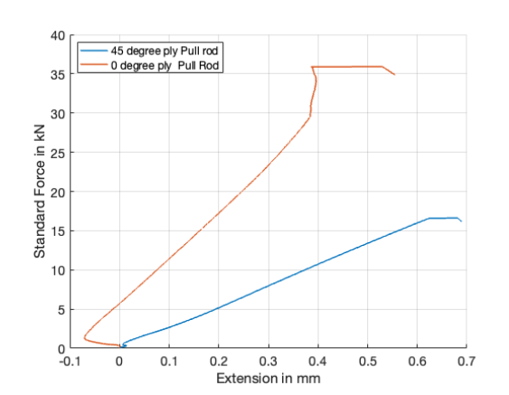
PEAK TEST LOAD
GENESIS GRM · MATLAB · ASTM TESTING · CFRP
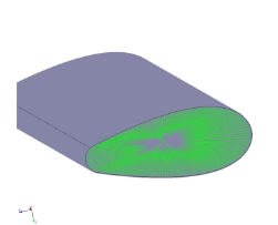
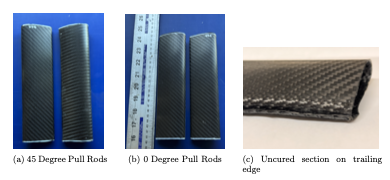
Manufactured CFRP suspension pull rods
01
ENGINEERING LOAD CASE
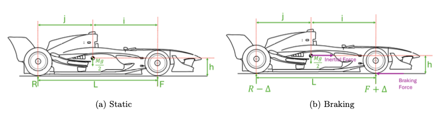
The front suspension pull rod was assessed under a severe braking
condition. Vehicle load transfer was used to determine the axial
force transmitted through the pull rod, while an eccentric load
case provided a representative torsional moment.
PULL-ROD FORCE
F
p
= ((F + Δ) μ) / cos(θ)
Calculated axial load ≈ 2.5 kN
TORSIONAL MOMENT
T = F
p
× e
Calculated torsional moment ≈ 2.7 Nm
Static and braking load cases used to define the pull-rod loading
02
MATERIAL CHARACTERISATION
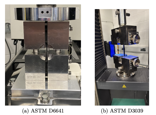
VTC401 CFRP was experimentally characterised before simulation so
that the material model was based on measured rather than purely
supplier-derived properties. Tensile and compression testing was
performed at 0° and 90° orientations.
ASTM D3039 tensile and ASTM D6641 compression testing
INPUT
GENESIS MATERIAL CARD
Experimental results were consolidated into a MAT8 material card
for the anisotropic composite model used in Genesis GRM.
Property
Value
E
1
55.3 GPa
E
2
55.4 GPa
G
12
26.5 GPa
ν
12
0.05
Density
1.80 g/cm³
Ply thickness
0.285 mm
The measured card also included longitudinal, transverse and shear
strength values for optimisation and structural assessment.
03
CAE METHODOLOGY
01
LOAD CASE
MATLAB calculations
→
02
MATERIAL CARD
Experimental inputs
→
03
MESH
1 mm nominal size
→
04
TENSION
Thickness optimisation
→
05
TORSION
RBE2 load application
→
06
OPTIMISE
Mass + ply orientation
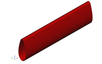
Tensile model — 1 mm mesh
Torsional model — RBE2 spider for central moment application
The optimisation objective was minimum mass. Tensile analysis varied
laminate thickness between 3 and 10 plies, while torsional optimisation
explored ply orientation between −90° and +90° in 5° increments.
04A
TENSILE OPTIMISATION
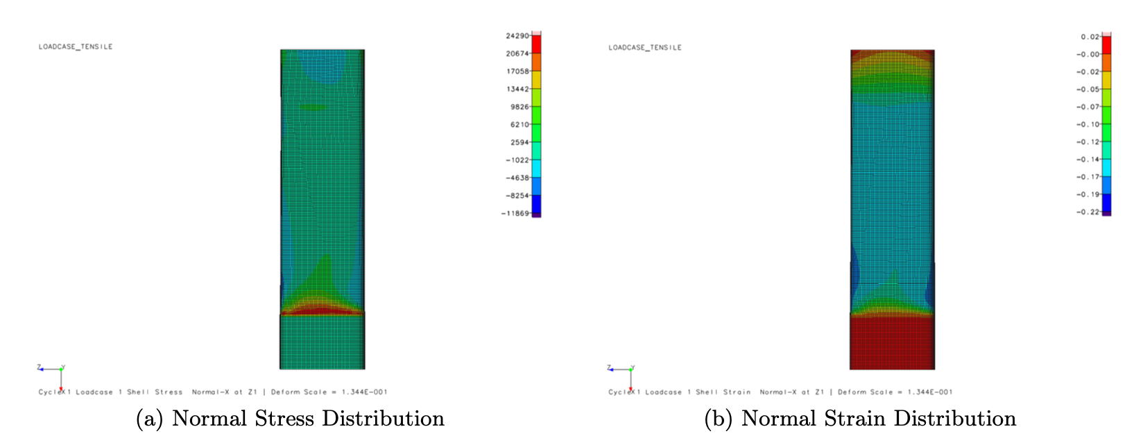
Genesis GRM was used to minimise laminate thickness while retaining
the required response under the calculated tensile load. The
optimisation converged on a three-ply laminate for the tensile case.
Tensile normal stress and strain distributions
3 PLIES
Optimised tensile laminate thickness
04B
TORSIONAL OPTIMISATION
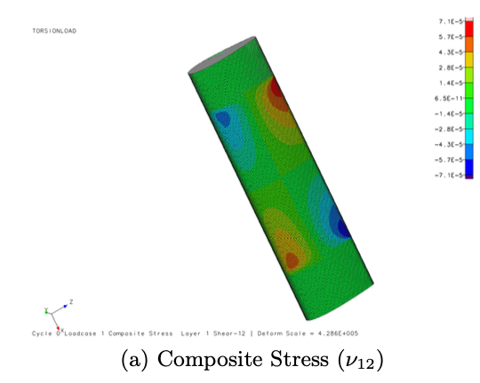
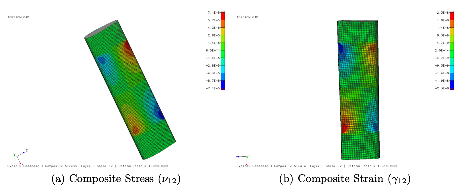
The torsional load case changed the optimum fibre strategy. Off-axis
plies were required to carry shear more effectively, producing a
layup dominated by ±45° orientations around a central 0° ply.
Ply-orientation optimisation under torsional loading
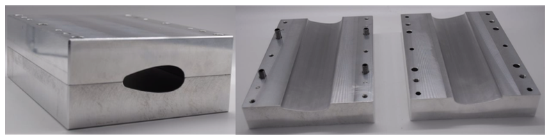
A CNC-machined aluminium split mould was developed to manufacture
the hollow aerofoil pull rods. The mould incorporated controlled
alignment and jacking features, while an internal vacuum-bagging
method was developed to consolidate the laminate through the
component's closed section.
CNC-machined aluminium tooling
Split-mould construction
Internal vacuum bagging
0° and 45° manufactured pull rods
Manufactured pull rods were physically tested in tension to assess
whether the laminate behaviour observed experimentally followed the
expected influence of fibre orientation.
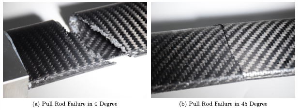
The test results showed a clear difference in failure mechanism.
The 0° specimen failed abruptly through the fibre-dominated load
path, whereas the 45° specimen exhibited greater delamination and
matrix cracking associated with off-axis loading.
Failure comparison — 0° brittle fracture vs 45° delamination
The physical testing supports the expected directional behaviour
of the laminates, while the limited sample count means the results
should be interpreted as validation of the engineering trend rather
than a statistically complete correlation study.
07
KEY TAKEAWAYS
01
TEST-DRIVEN MATERIAL MODEL
Experimental characterisation provided the material inputs
used to build the anisotropic Genesis GRM model.
02
LOAD-SPECIFIC LAYUP DESIGN
A 0°-dominant laminate suited tensile loading, while ±45°
fibres became important when torsional shear was introduced.
03
CAE TO PHYSICAL VALIDATION
The project linked analytical loading, experimental inputs,
simulation, manufacturing and physical component testing.
“This project demonstrated that composite optimisation cannot be
separated from material characterisation and manufacturing. The
confidence placed in the CAE model depended directly on the quality
of the experimental inputs and the ability to reproduce the intended
laminate physically.”